TOP 5 Heat Sinks TOP 5 Low Profile Heat Sinks TOP 5 Liquid Coolers
Heatsinks by Brand / Mfgr Reviews + Articless Advanced Search
|
TOP 5 Heat Sinks TOP 5 Low Profile Heat Sinks TOP 5 Liquid Coolers Heatsinks by Brand / Mfgr Reviews + Articless Advanced Search |
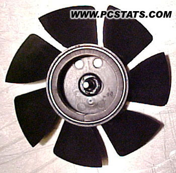
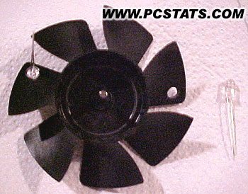
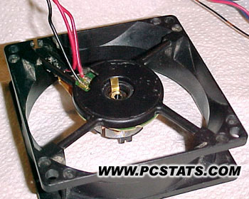
Anyway, here are the steps we went through to add the gift of blue light to a standard 80mm 12V fan. There have been other people who thought-up and built this kind of a fan mod before, but this is our take on the whole procedure. 1. Remove the sticker on the bottom of the fan motor to gain access to the motor spindle compression fitting. Depending on the type of fan, this can be a circular compression clamp, compression fitting, or lock washer of sorts. To release the impeller blades from the motor, this locking ring needs to be removed first.
2. With the motor spindle locking mechanism removed, separate the impeller blades from the fan motor and drill a hole through the top of the casing. This hole should be close to the edge of the central impeller assembly. The reason for this hole is that you will need to insert a small screwdriver in to push out the circular magnet and its' metal casing (they should be one part). With the magnet removed from the impeller assembly the modifications can begin!
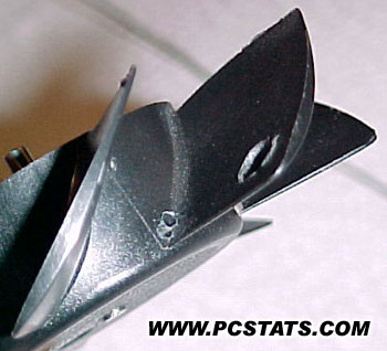
3. The first step is to drill a hole for the LED in two opposite fan blades. The size of the holes will depend on the size of LED you have, but they should match up as best possible. Next switch to a smaller drill bit, of about 1/32, and drill two very small, closely spaced holes close by the leading edge of the fin in the central cylinder of the impeller. These two holes are for the wires of the LED to pass through. They should be as close to the top of the central impeller cylinder so as not to interfere with the magnet when it is reinserted.
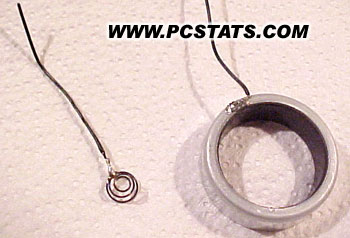
4. Remove the small spring from the impeller assembly and solder two short lengths of wire to either side. You many have an easier time soldering the wire to the metal if you sand it a bit with some 600grit paper. Also remember that the size of the solder ball should be as small as possible. If you're messy and leave a big glob of solder it will interfere with the spring compressing and may cause the entire impeller assembly to sit high as a result.
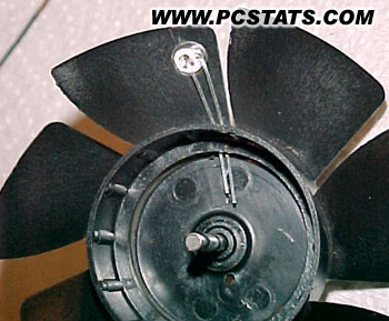
5. At about the same position as the holes you drilled for the LED wires, solder two wires to the top of the metal magnet casing. When the magnet is reinserted into the impeller assembly the two wires you've just soldered on should line up with the holes drilled for the LED wires. 6. Insert your LED's into the holes that you previously drilled in the two fan blades, and thread the lead wires through the two sets of small holes in the central impeller assembly. If you have some small gauge heat shrink tubing it is a good idea to insulate one of the LED lead wires to prevent any possible shorting which may occur.
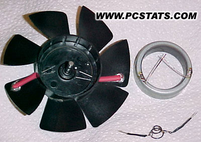
7. Insert the magnet back into the impeller assembly and line up the soldered areas with the wires from the LED's. Next, drop in the small spring and orient it so that the wires match up as well. The next step will be to begin soldering the contact wires, but it is very important to remove as much excess wire as possible before continuing. If there is any loose wire it may snag on the motor windings and prevent the fan from doing much of anything.
8. With the wires trimmed to the absolute necessity, begin soldering the negative lead wires to the small spring in the center of the assembly, and the positive lead wires to the metal magnet casing. It is worthwhile to double check which wire is which on the LED before going ahead at this point. If the LED's don't light up when you apply current to the metal spindle, and the metal magnet casing then something awry. Double check your connections and fix the problem before moving on to the next step. 9. For the blue LED's to light up they need electricity. Obviously, if we
were simply to attach wires directly from the LED's to the battery the fan would
not be able to rotate. By soldering one set of lead wires to the metal magnet
casing and the other set to the spring around the motor spindle we have created
electrical paths. All that is left to do is to wire from the fan motor assembly
to corresponding parts to complete the electrical circuit.
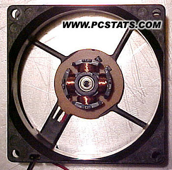
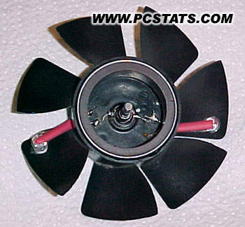
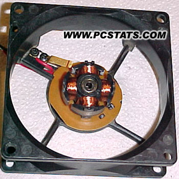
10. The negative power hook up will be delivered to the motor spindle from the ball bearings. Either insert a thin piece of contact wire between the bearing and the plastic, or solder a wire to the outside of the bearing casing. Don't solder to the top or inside casing of the bearing or it won't work. A resistor of appropriate strength should be attached to this point and soldered to the negative power terminal for the fan.
11. The positive power hook up will be delivered by a spring, or other type of brush type device to the edge of the metal magnet casing. How you set this up will depend on what you use. In our case we used a gold-plated leaf spring set so that it would ride along the edge of the metal magnet casing as the impeller rotates. This spring is connected directly to the positive power terminal by a short wire. Other possible hook ups could include braided wire for example. Whatever you use, it is important that it make continuous contact with the rim of the metal casing or the LED's will switch on and off as the impeller rotates. Chances are that a little tweaking to the magnet casing will get it to seat more evenly and improve the connectivity of the positive power hook up.
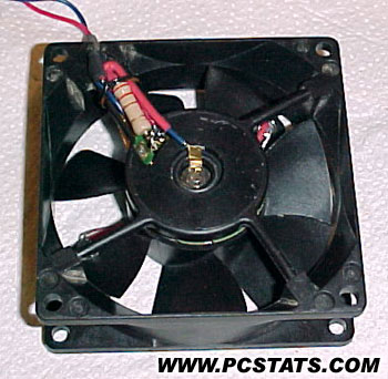
12. The last step is to reattach the impeller assembly to the rest of the fan and ensure that it can still rotate freely. If any wires are causing interference, now would be the time to fix the problem. With the fan pressed down, reattach the spindle compression fitting or lock washer. With one last check of the connectivity of the positive power hook up all that is left is to power up the fan and revel in its glowy goodness.
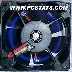
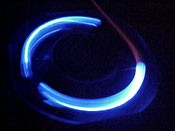
If everything works, you should have one devilishly cool circle of blue light emanating from the fan as it spins away cooling your case, power supply, or whatever. Congratulations you've just made your first Glowy Fan!
|
|
|||||||||||||||||||||||||
|
Find a Heatsink . Latest Heatsink Reviews . Top 5 Heatsinks Tested . Top 5 Low Profile Heatsinks . Top 5 Liquid Coolers . Heatsinks by Mfgr / Brand |
Social Media |
FrostyTech.com Info . Feedback . Contact Us / Heatsink Submissions . Submit News . Privacy Policy |
 | |
© Copyright 1999-2025 www.frostytech.com All Rights Reserved. Privacy policy and Terms of Use Images © FrostyTech.com and may not be reproduced without express written permission. Current students and faculty of accredited Universities may use Frostytech images in research papers and thesis, provided each image is attributed. | ||||
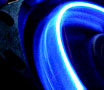
 Meet
the Glowy Fan
Meet
the Glowy Fan